Fix the pumps

Wednesday, April 18, 2007

11 spills and counting

Yet more pump testing, and yet more oil spilled.

The last reported spill was January 25, 2007. This time, it was on March 24th, when the Corps was testing their supposedly "fixed" pumps at 17th Street that are all going to be ready on June 1.

March 24, 2007
Quantity released: 50 gallons
Description of incident: The caller stated that while testing a pump, a hydraulic line failed and caused a release of hydraulic oil into the canal. The release is secured and booms have been placed.
Sheen size length: 40 feet.
Sheen size width: 30 feet.

The is the seventh reported spill at the 17th Street site, and the eleventh spill overall at all three floodgate sites. Ten have been reported to the National Response Center, while an eleventh (on September 15, 2006 at the London Avenue site) remains unreported except in the media.

With this spill, the total amount of hydraulic oil spilled into all three outfall canals is now approximately 800 gallons (it's 775 gallons without the September 15th spill). That's almost 20 barrels.

What's bothersome about this one is that the Corps was testing supposedly refitted and repaired pumps on March 24th. Why are their hydraulic lines still leaking? Is it the pipes or the hoses that are failing (unclear from the spill report)? We know there's certainly the possibility of the pipes failing. Also note that report says the leak happened during operational testing, not while the pump was being installed or removed or other somesuch circumstance.

For the record

I need to post some corrections to my earlier post regarding sizing of the hydraulic pipes. While my conclusions remain correct, my methodology was incorrect in some respects.

First off, I cited the wrong standard. Instead of ASME B31.1, I should have cited ASME B31.3. That's because B31.1 is used for power piping (boilers, etc.), while B31.3 is used for process piping, which is what we have at the floodgates. However, the formula to figure out the required thickness of a pipe is still the same in each standard. It's the following:

T > t + c

The left side of the inequality represents the actual, physical diameter of the pipe as it's received in the field. The right side is the calculated minimum thickness, which - because it is a minimum - must be less than the real thickness of the pipe.

Pipe is made with a certain tolerance. In the case of standard carbon steel A106B pipe, like what we have here, the tolerance is +0,-12.5%. That means that while the nominal thickness might be "X," it could be "X" minus 12.5% of "X," or 0.875 times "X." For 3" schedule 80 pipe, the nominal thickness is 0.3". But when manufacturer's tolerance is included, the actual thickness could be 0.875 x 0.3, or 0.2625". This is the thickness we must beat on the right side of the inequality. If we don't, then the next highest thickness should be chosen.

On the right side of the inequality "t" can be found using the following B31.3 formula:

t = P*D/(2*(S*E+P*Y))

where each of those letters represents the following:
P = internal design gage pressure = 3000 psi
D = outside diamter of pipe as listed in tables of standards or specifications or as measured = 3.5"
S = stress value for material from B31.3 - Table A-1 = 20,000 psi for A106, Gr. B
E = quality factor from B31.3, table A-1A or A-1B = 1
Y = coefficient from B31.3, table 304.1.1, valid for t less than D/6 and for materials shown = 0.4

t = 0.2476"

Ah ha! It would appear the pipe is fine. 0.2476" is less than 0.2625". Case closed. Move along here, nothing to see.

Before I debunk that, let me point out another of my previous errors. Previously, I used 15,000 psi as the stress value for ASTM A106, Gr. B. That's the value from the material table in standard B31.1. However, in B31.3, the corresponding value is 20,000 psi. All other values in the equation above are exactly the same.

Now, what about the apparent victory for Corps/MWI engineering? Well, there's still the matter of "c" in the original equation. Little "c" is the sum of mechanical, corrosion, and erosional allowances. These are additional factors which take into account wear in the pipe and threadedness. We have seamless welded pipe, so I'm going to generously not include any mechanical allowance. However, we obviously have corrosion, and we also have erosion. Both are natural processes of fluids flowing through pipes. Normally one only has to worry about such things happening on the inside of the pipe. However, the corrosion in this case is unnaturally bad, since corrosion protection has not been applied to the pipe for over a year.

Picking corrosion/erosion allowances is part art and part science, and I'm not going to pretend to be an expert on it. I've seen numbers ranging from 1/32" (0.03125") all the way up to 1/8" (0.125"). From what I understand, 1/8" is pretty stringent, usually being used for salty environments such as an offshore platform. However, one can see that even applying the smallest of allowances pushes the calculated minimum thickness above 0.2625". So what I thought I'd do is just lay out the results for various allowances:

1/32": t + c = 0.2788"
1/16": t + c = 0.3101"
3/32": t + c = 0.3414"
1/8": t + c = 0.3726"

All of these are greater than 0.2625", and most are greater than 0.3". Thus, the pipe is not up to the applicable code, and a greater thickness should have been used.

Then, going one step further, I subtracted the various corrosion/erosion allowances from the actual pipe thickness (0.2625"), and calculated the actual pressure rating of the pipe:

1/32" allowance (wall thickness = 0.23125"): pressure rating w/ existing pipe: 2790 psi
1/16" allowance (wall thickness = 0.2"): pressure rating w/ existing pipe: 2395 psi
3/32" allowance (wall thickness = 0.16875"): pressure rating w/ existing pipe: 2006 psi
1/8"allowance (wall thickness = 0.1375"): pressure rating w/ existing pipe: 1622 psi

All of these are less than 3000 psi.

What these results say is that while the pipe is okay when you first load it with fluid, you can't actually flow any fluid through it at pressure for the anticipated life cycle (regular maintenance runs a few times a year, plus one or two storm events a year, for an indeterminate, but ever-increasing, number of years; the Corps now says to expect permanent pumping stations in 2012, and frankly it's not clear that the current installations won't be part of those stations). So the piping's kind of useless in its current application.

Keep in mind I've been pretty conservative in this analysis. The fact is that the hydraulic pumps on the drive units can put out more than 3000 psi. Also, the pipe is currently rusting every day at an unknown rate. Also, there are unaddressed flaws in the piping where welding rods, welding torches, and steel-toed boots have locally deformed it. At those points, where the wall thickness could be considerably less than 0.2625", all bets are off.

There's one other correction I need to make. I earlier said that the pipes could burst if put under pressure. That's not technically true. For a pipe to burst, it would have to have its yield strength exceeded. The yield for A106B is 35,000 psi, far higher than the minimum tensile strength of 20,000.

What could happen is the tensile strength is exceeded? It could put failure stress on welds and on areas of local deformation. It could also weaken the elbows in the pipes. In any case, what it boils down to is that there is no factor of safety built into the thickness of the pipes, and they can't be trusted. After all, would you trust a system to protect an entire city that can't even protect itself from rust?

Thursday, April 05, 2007

More on the pipes ... and rust

Updated 6/11/08. See below.

Updated 5/27/08. See below.

Updated 10/3/08. See below.

As promised, I wanted to show pictures of the hydraulic pipes, so people can get a better feel for what I'm talking about.

First, let me point out where they are:

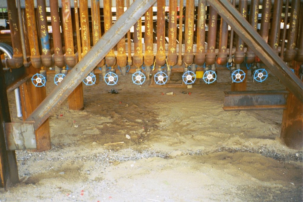
This is the east bank of the Orleans Avenue canal floodgate site. I'll be returning to this picture in a later post to talk about some details on the elbow, but for now, it serves to help place the hydraulic lines in context.

Let's look at a closeup:


First off, I've noted the confirmation that the high pressure lines are schedule 80 with a white rectangle.

You can see other pipes from 17th Street also marked as "Sched 80" on this picture from my September 30, 2006 post:


For reference, the pipes marked "Sch. 40" are the schedule 40 low pressure lines coming back to the drive units from the pumps. The schedule 80 pipes are the high pressure lines going out to the pumps from the drive units.

What is obvious, but somehow has escaped everyone's notice until now, is that the pipes are unpainted, and have been since they were installed almost a year ago. Naturally, they're rusting.

Here's two more closeups of the Orleans Avenue pipes:


You can see dings and marks all over the pipes. I'm not sure what they are. They could be areas that were struck by the welding torch or the welding rod during welding. Or they could be marks where tools or other pipes hit during assembly or shipment. They could be points of local thickness loss; I'm not sure.

I can bet the marks are even worse at the 17th Street site. Remember my post last October about lack of fall protection? That has pictures of the installation contractors walking all over these pipes up in the rack. Such behavior would never be tolerated in private industry.

I've been looking at this situation since the lines were installed. I've always thought the pipes were eventually get painted, despite the difficulty in doing it after they were installed (normally, on any job, pipes are sandblasted, primed and painted in a shop before they are shipped to the job site. That wasn't done here.). Despite all the dignataries, Senators, Representatives, Corps officials, press, and contractors that have passed through these three sites over the last year, it seems inconceivable that no one has asked, "Aren't the pipes going to be painted?" However, here we are almost a year later, and I think we're stuck with these unpainted pipes for the coming storm season, as well as the three following that. I think it would be nearly impossible to sandblast and paint the pipes on the interior of the pipe racks without disassembling the ones on the outer perimeter. Plus, doing it over water introduces a whole new set of complications. So obviously the pipes, which already have walls that are too thin for 3000 psi service, are going to continue to rust, further thinning the walls.

Just so you know, here's what the bid specifications say about the pipe:


"Supply pipe shall be ASTM A106, Schedule 80 seamless black steel pipe, and return pipes shall be ASTM A106, Schedule 40 seamless black steel pipe. All hydraulic pipe shall be pickled, oiled and plugged (P.O.P.)."


There's no mention of painting, which is weird. Nearly every pipe specification I've ever seen discusses painting. I've helped write both paint and pipe specs, and have read numerous ones during those jobs. There's tons of standards and other publications on this stuff from SSPC.

Also, here's the relevant portion about painting from chapter 12, "Corrosion Protection," in the Corps' Engineering Manual that deals with piping, EM-1110-1-4008, "Engineering and Design - Liquid Process Piping:"


12-1 Corrosion Protection
[...]
b. Above Grade Installations
The external surfaces of metallic piping installed above grade will also exhibit electrochemical corrosion. The corrosion rate in air is controlled by the development of surface-insoluble films. This development is, in turn, affected by the presence of moisture, particulates, sulfur compounds, nitrogen-based compounds, and salt. This corrosion is typically uniform, although pitting and crevice corrosion are also common. Besides selecting a material of construction that is appropriate for the ambient environment, the primary method of corrosion control in above grade piping system is the application of protective coatings.


I don't know why such a simple thing as painting the pipes to keep them from rusting has been neglected. It doesn't make sense. However, physics and electrochemistry will not stop because of whatever excuse the Corps gives. The pipes will continue to rust in a moisture-rich environment.

This isn't the only rust on the system. Look back at the shot with the duct tape in my post two posts ago :

You'll notice the bolts are also rusting. There seems to be rust on the flanges as well.

Those bolts should have been stainless steel. The coal tar-like coating on the pumps should have been waterproof. But once again, skimping by MWI left the bolts as carbon steel, and I don't think the coating's holding up either.

This is so basic, that I think it's escaped everyone's notice until now. After all, who would leave these pipes to simply corrode? It sounds crazy. But I'm forced to ask, are we supposed to have confidence in a system that isn't even protected from the moisture in the air? At this point, the only way to restore that confidence is to ultrasonically or radiometrically test every foot of the 17,000 feet or so of high pressure line, and then release the results to the public immediately. Short of that, there is no conclusive way the Corps can say that the pipes - as they exist today, not when they were delivered - are the thickness they were specified as. Of course, even if they are that thickness, they're still too thin, but that's another kettle of fish.

Update 5/27/08

Over two years after the rusty pipes were installed, the Corps has finally decided to address the corrosion problem. The more fundamental problem of the pipes being undersized will go unaddressed.

On May 23, 2008 a presolicitation was issued to hydroblast and paint all the hydraulic and fuel lines at all three outfall canals:

New Coating System for Hydraulic Pipes-Cleaning and coating hydraulic and fuel lines Interim Closure Structures-Orleans Avenue, London Avenue, and 17th Street

Of course, they're not exactly moving at light speed. The presolicitation indicates that potential bidders will have until half way through the peak of hurricane season (July 31, 2008) to get their bids in, and the contract would probably be issued weeks after that, meaning that the pipes will continue to rust for many more months.

One other thing: this means the Corps is literally covering up the problems with the pipes.

Update 6/12/08

Further documents for the pipe painting job have been issued. They are a treasure trove of information.

Both the specifications and drawings have been placed on line:

Specs: https://www.fbo.gov/utils/view?id=7e334641286b8cb4daba96f2fdcaf561
Drawings: https://www.fbo.gov/utils/view?id=f654bc8f34386efd84e6fe67abbea8f3

The scope of the job is gigantic. Just about every pipe on all three floodgate sites must be hydroblasted and painted. It is shameful that this much work has been delayed for this long, while the pipes have been rusting for years.

However, while the information associated with the solicitation is interesting in its own right, what attracted my attention is that many of the drawings are actually collections of digital pictures of the three sites.

According to the date stamps on some of the pictures, they were probably taken in December of 2007.

I'd like to zero in on one picture in particular: picture 2 on sheet 32 (drawing M-30):

The two areas highlighted in red are what I'm interested in.

The top area shows...

duct tape.

The bottom area shows...

Rope suspending hoses which convey hydraulic fluid to and from the pumps. Not steel, but rope. I hope those knots are tied tight.

My guess on the reason those ropes are there? Two winters ago, the Corps pulled the pumps to install extended piping on them which moved the previously submerged hose connections out of the water (to prevent further rusting of the fittings as captured in the pictures above). They probably decided to reuse the same hoses.

Before, those hoses ran from the deck above down to fittings which were underwater. With the extended piping, there was a shorter distance between the pipe on the deck and the new connections on the pumps. But they still had the old hoses, which were now too long and heavy, and they needed to make sure the hoses were not pulling down on the new fittings. So they roped them up. Hardly the best solution, and one has to wonder how well the ropes will hold up in extended storm conditions with the pumps running for eight or twelve hours.

Other possible solutions?
1) Fabricate shorter hoses
2) Run the piping above the deck and hard pipe the entire system except for standard flexible connections. That is, eliminate the hoses. That would make it more difficult to maintain the pumps, but would make their operation a little more reliable.

Another picture in the drawing package caught my eye. It is picture 33 on sheet 69 (drawing M-67):


The hose on the left is a hydraulic fluid hose leaving the drive unit, meaning that the pressure of the fluid is at its maximum at that point.


The labeling on the hose says the following:
3000 PSI (21.0 MPa) MAX

That's interesting, because there are red signs on all the drive units:


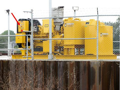
which say the following:

DO NOT EXCEED 3200 PSI

or 200 psi more than the rating of the hose.

When one has a piece of equipment with a rating of "X" psi connected to another piece of equipment that can generate "X" + 200 psi, one should not be exceeding "X" psi. Or else, one might damage the hose and take a pump out of service.

Would it have cost that much more to provide hydraulic hose with a rated pressure greater than the rating of the pump feeding it?

Update 10/3/08

The Corps took its sweet time awarding this one, finally announcing it on October 2nd, 2008:
Contract award for new coating systems (sandblasting and painting) at New Orleans outfall canals

With the actual document to be found here.

I assume the Corps realized it would be foolish to have contractors out in the middle of the canals during the height of hurricane season. Of course, considering the pipes have been rusty since they went in over two years ago, it's not like they didn't have time to do this work last winter and spring. Or perhaps even before the pipes went in...

Anyway, the work's (contract W912P8-09-C-0001) been awarded to Creek Services out of Gretna, just across the river. Creek Services is a favorite contractor for the Corps in New Orleans, doing tens of millions of dollars in business since Katrina. This contract, at a value of $1,972,867, is peanuts for them.

Interestingly, the Corps posted the bid summary as well:
Bid summary for pipe coating systems

With the actual document here.

The bids were opened July 7th, 2008.

It appears there were only two bidders. Creek Services and Truckla Services of Vicksburg. Truckla was actually a little cheaper than Creek.

The contract can be found here.

[Update 6/1/11]

Over the years, the Corps protested publicly that these pipes were adequate, even though the most basic of calculations show they are not.

They even tried that with their own consultants. In 2006, the Corps had their outfall canal consultants Black & Veatch investigate ways to reduce the costs of the permanent pump stations. One scheme was to reuse parts of the Interim Closure Structures. The resulting report, dated December 12, 2006 and titled the "Alternative Considerations Report," detailed what B&V thought of various components of the ICS's. As such it is a contemporaneous account of design deficiencies. Here's what B&V wrote about the hydraulic piping:
"The field staff indicated that the hydraulic piping wall thickness is sized for the rated pressure of 3500 psi and has little to no extra wall thickness for corrosion. The piping is not coated and could soon begin to reduce to the safety factor and eventually lead to failure. The adequacy of the wall thickness for the discharge piping was not determined but it is not coated and could pose problems as corrosion reduces the wall thickness."

So the "field staff" either lied or didn't know about the inadequate sizing. However, they did know the pipe effectively had no corrosion allowance. That's yet another problem the Corps knew about at the time, but waited years to address, and even then literally only covered up the problem rather than addressing it fully.

Monday, April 02, 2007

Oh. My. God.

Corrections have been made to the post below. They can be found here. Note that conclusions remain true, it is merely the methodology which was partially in error.

This one is aimed at the engineers in the audience, but everyone has to read it.

We know the following information about the welded pipe that runs from the drive units to the pump units, conveying the high pressure hydraulic oil to spin the pump impellers:

Max working pressure = 3000 psi (actually can go higher, see Ms. Garzinos's memo)
Diameter of high pressure line = 3" (see the Floodgates Operating Manual)
Thickness of high pressure line = Schedule 80 (nominally 0.3") (See the original specs, or the job sites. "Schedule 80" is written all over the pipes, which are plainly visible from the levees at Orleans Avenue. I have pictures, which I will post later)
Material of high pressure line = A106, probably grade B (See the original specs), with Maximum Allowable Stress in Tension of 15,000 psi [corrected to 20,000 psi here]
Pipe supplier = MWI (See the original specs)

Engineers in the audience will know to run the numbers through equation (4) in section 104.1 of ASME B31.1 [corrected here]. This is an equation that has been around for decades and is well known to every engineer who has ever specified pipe.

When you run that calculation with just the standard numbers (assuming a standard 12.5% wall deviation, joint efficiency = 1, y = 0.4), you find something absolutely horrifying.

The pipes are too thin to take the normal operating pressures! They're too thin by a lot. When you run the numbers, you find that the maximum burst pressure for 3" Schedule 80 A106B pipe is only 2393 psi [corrected here]. Even if the material is actually A106, Grade C, that still only gets you to 2791 psi. Even when you knock the wall allowance out completely, you still don't get there. When I did this calculation, I actually felt physically sick when I got the result. I've redone it a few times, hoping the numbers were different. They're not. And keep in mind that the pressure can exceed 3000 psi during operations, as also shown in Ms. Garzino's memo.

There are two of these lines on every pump/drive unit pair, each of them about 250 feet long. There is over 17,000 feet of this pipe installed at all three floodgate sites. All of it is unfit for the service it will see. All of it is prone to bursting under normal service [corrected here]. How this could have slipped through so many layers of review is unknown, but I can tell you that if there was a "Fitness for Service" declaration signed, it must be either fraudulent or signed under duress. I bet that the welders working these jobs probably asked for some kind of release from liability, so they wouldn't be blamed when the pipes burst. This is the worst kind of engineering mistake. This is "crash-into-Mars-because-we-didn't-convert-the-units-correctly" stuff.

This is equivalent to driving the sheet piles too shallow on the levees. It is a fundamental flaw in the system that has not been addressed by anyone, and has most likely been covered up to have gone this long. And it could have been remedied so simply: the Corps should have specified Schedule 160 pipe instead of Schedule 80 (by the way, there are questions to be answered as to why a thickness for the pipe was specified, but no diameter. That's very unusual. It's almost like the Corps knew in advance what they were going to get before they issued the specification...).

For reference, I suggest you take a look at this company's website:
Redox, Inc.

This page on their site is particularly instructive.

I have no association with them, other than they happened to have all the information that makes my point - conveniently organized and well written.

This is so incredibly shocking it bends the brain. It appears that the Corps and/or MWI didn't do the simplest of calculations involved in sizing a pipe. Any newly minted engineer who does anything with piping becomes familiar with this equation within five minutes of being handed a job. By the way, that calculation is also called for in the Corps' own engineering manual dealing with piping, EM-1110-1-4008, "Engineering and Design - Liquid Process Piping." It shows up on page 5 [correction: page 16] of chapter 3 (note that the Corps wrote the manual on WordPerfect, so the characters for plus, minus, and equals won't show up properly in Adobe Reader) [correction:

Put simply, all of the pumping systems, as designed, procured, and built, have a strong likelihood of failure when placed under normal operating conditions.

[Corrections to this post are available here]

Sunday, April 01, 2007

Would you buy a used car from these folks?

[UPDATE, June 4, 2010: Many of the conclusions in this post have been superceded by my May 27, 2010 post, "How did the pumps get from...". I have seeded updates through the post to provide perspective.]

There's been a lot of talk since the story about the defective MWI pumps broke on March 12. And while the media and the Corps have covered various aspects of the story around the pumps, no one has publicly looked at the system itself to figure out exactly what problems may still need to be addressed. Fortunately, nearly everything about the system is fully on display for anyone to walk up to and examine.

Over the next few posts, I'm going to be concentrating on specific deficiencies in the design of the pumping system. Some relate to fabrication, some relate to engineering design, and some relate to installation. This is nitty-gritty stuff that engineers love (or should love) to dig into. Keep in mind that engineering is not a static field - it is subject to opinion on how to do things the best way. These are my opinions, backed up with my experience as a mechanical engineer and consultations with others familiar with similar installations. Some of this may seem a bit didactic, but I'll always show that there's a point.

I'm going to start with the pump units themselves. As a refresher, you may wish to read my earlier post about the fundamentals of how the pumps and their drive units are set up.

Out at the Orleans canal floodgates, all ten pumps have been pulled in anticipation of refits by MWI. The five west pumps were pulled Wednesday, March 22. The five east pumps have been on the deck since last October. They're all up on the deck on the east (Marconi Drive) side, and anyone can go up and check them out. So I did so last Sunday. So did at least five other people while I was there, including two joggers with their dogs.

Frankly, the workmanship is ... not great. Let me lead off by showing you something that I had to laugh at to keep from crying:


Yes, that's duct tape wrapped around a hose meant to hold at least 1000 psi of hydraulic oil (I think - I'm not sure of the pressure on the outlet of the coolers). To top it all off, that particular fitting sits below the waterline when the pump is in the canal. Are they kidding us with this?

[UPDATE: This hose fitting appears to be one of the ones on the east pumps that were sandblasted and painted during October, 2006 as a first cut at repairing corrosion damage on the hose fittings. The duct tape may have been acting as masking for the painting and sandblasting, or it may have been part of the protection. One can see what also appears to be duct tape on other painted fittings in this shot from October, 2006:


There's more details on this hose fitting painting scheme and how it fits into the overall corrosion chronology in my May 27, 2010 post, "How did the pumps get from...". I don't think this particular method of corrosion repair ever ended up back in the water, though see the UPDATE further down that speaks to confusion over this.]

Allow me to further explain what you're looking at in that picture. The black piece is the fitting between the hydraulic hose coming out of the discharge of the Rineer hydraulic motor and the inlet of one of the two hydraulic coolers. The hose comes down from the top of the frame, and the duct tape is around the very section where the hose joins the fitting. I couldn't believe what I was seeing when I snapped this picture.

Let's step back a bit. Here's a picture of three of the five west pumps (the ones that were just pulled out of the canal last week):


I've noted the location of the typical waterline, which is based on the growth of those little barnicle things all over the pumps. As you can see, the fittings joining the hoses to the hydraulic cooler inlets on these pumps have all rusted. Here's a close-up of another cooler fitting from a west pump:


What is more surprising [UPDATE: This should read "perplexing," and it is explained in the next UPDATE paragraph as being in the "splash zone"] is that the fittings on the discharges of the coolers - which for most of the last year have been above the waterline, and thus only exposed to air and humidity - have also rusted. How could this happen? These pumps have only been in the canal since last June.

It's pretty simple. It appears that the manufacturer, MWI, skimped on the purchase of those fittings, buying carbon steel instead of stainless steel despite knowing they would be exposed to water all the time. Curiously, the Corps' specifications are oddly silent on the material of the hose fittings:
"2.4 Hydraulic Piping and Hose: ... All reinforced supply hose shall be double wire braid reinforcement and shall have minimum safe working pressure of 3,000 psi. All pipe fittings shall be socket weld type (with socket weld to thread fittings at conversion point of pipe to reinforced hose)..."

Considering the criticality of the installation (protection of life and property), use of stainless steel fittings in this application to prevent corrosion should have been a no-brainer.

[UPDATE: This very issue was the subject of considerable debate between the Corps and MWI at the time. The fittings are zinc-plated steel, and obviously could not hold up to brackish water, whether immersed or in the splash zone (the area above the water line, but subject to spray and waves, which are just as corrosive). However, MWI stated that since the plated fittings were part of their standard pump package, they were under no obligation to supply anything better. Of course, since the Corps copied and pasted MWI's specs for the standard package, it shouldn't have been a surprise that the pumps wouldn't work very well in conditions for which the standard package is not designed. Also, MWI claimed they didn't know the water was salty, so why would they provide anything better than what they thought was needed for fresh water?

Again, it's best to read over my May 27, 2010 post, "How did the pumps get from...". Also, the letter MWI sent to the Corps at the same time the Orleans Avenue east pumps were initially on the deck (during the period when the Corps and MWI were trying to figure out what to do about corrosion) is quite illuminating. It can be found starting on page 201 of the complete MWI contract file]

You may be asking, why is the fitting in the duct tape photo not rusted? I believe that fitting is on one of the pumps which has been out of the canal since October (the ones from the east side of the project), so it was only in the water for a little over four months. The pumps shown in the other photos have been in the water for approximately ten months. This is troubling, since the expected service life of these pumps is about four years - the Corps has promised permanent pump stations at the lakefront by the end of 2010.

[UPDATE: We now know the fitting in that picture was painted after being removed from the water in September. It was rusty before that. Also, thanks to tons of delays by the Corps, the permanent pumps are now not scheduled to be on line until the 2015 hurricane season.]

There is another possibility why the fittings on the east pumps don't show rust: they leak so much hydraulic oil that rust cannot form. There is some evidence for this. Below is a picture of one of the east pumps (which has been on the deck since October). I've highlighted the fitting on the discharge of the cooler.


Here's the highlighted area blown up:


I've noted the places where oil has apparently leaked.

[UPDATE: This is curious, because this photo is of one of the pumps from the west side of the site. It was pulled up in March, 2007 ahead of the piping extension repairs mentioned below and detailed in my May 27, 2010 post "How did the pumps get from...". Yet the hose fitting I've highlighted appears to have been sandblasted and painted like was done to the fittings on the east side pumps back in October, 2006. It's difficult to figure out, since the contract documentation gives the impression the sandblasting and painting technique was only done on the five east pumps. I'm not sure what to make of this.

However, the idea that the photo also shows evidence of leaks on the oil cooler is eminently possible, especially after reading about the repairs to the pumps in 2009 and 2010. The 2009 Conhagen report of repairs to 17th Street pumps E5 and E7 mentions weld repairs to the coolers. In the 2010 repairs, the coolers were apparently so corroded that they were completely replaced with stainless steel units.]

This is not good manufacturing. Material selection is a pretty easy part of the engineering on this job, and it appears the ball was dropped. It certainly brings into question the quality of the work elsewhere on the job.

This part of the story may have a happy ending. As part of the refits the Corps and MWI are undertaking - apparently at the shop of Associated Pump & Supply in Houma, LA - all of the below-the-waterline connections which previously were between hose and pipe have been replaced with hard pipe, whioch hopefully won't leak. Now all the pumps have pieces of pipe sticking up out their sides, terminating with connection points which will be above the deck on the support platforms. Frankly, this should have been done in the first place by MWI, and if they knew there were going to be connections which remained underwater constantly (which they did, since the pumps are designed to be immersed in the canal), those fittings should have been corrosion-proof. That means using stainless steel, which is the industry standard. Keep in mind that none of this has ever been acknowledged as a problem by the Corps.

[UPDATE: It was never acknowledged, but it was paid for, to the tune of over $500,000 for the piping modifications. And those modifications turned out to be nearly an entire waste of money, because while the elevated hose fittings may have been a little further from the brackish water, the entire rest of the pumps were completely corroding to bits just two years later.

See my May 13, 2010 post, "Imminent," my May 27, 2010 post, "How did the pumps get from..." and my June 3, 2010 post "This year's scramble" for the results of the total lack of consideration on dealing with corrosion in the late 2006/early 2007 timeframe. They screwed this one up big time, and then used permanent pump station money for the "fix," which in some cases was no fix at all.]

In future entries, I'll be looking at other problems with the pumping system. There are many, and none of them have been acknowledged by the Corps.

Go to older posts Go to newer posts